|
 |
home » Embedded Target for dsPIC » Examples » IMU |   |
|
|
IMU |
|||||||||||||||||||
|
!!! THIS PAGE IS NO MORE UPDATED !!! Click here ==> GO TO THE NEW IMU PAGE
The micro-Inertial Measurement Unit (IMU) measures the absolute angle (or attitude). It is made of
Fusing the rate gyro information with the accelerometer information provide a better estimation of the roll and pitch angles.
Fusing speed rate with acceleration ?Angle estimation using rate gyro data only : The initial value of the integrator must be equal to the initial angle of the rate gyro. Speed rate is then integrated to track the angle. However, non zero mean error of the rate gyro, due to temperature drift, is integrated. This integration of error induced an unrecoverable bias. Also, The initial value are impossible to set without additional sensor. Angle estimation using accelerometer data only : Accelerometer sense the gravity acceleration added with the acceleration of the sensor itself. Decomposing the gravity vector on the accelerometer axis is unique except for the yaw rotation axis. The resolution of the roll and the resolution of the pitch angle is done using the atan function. Note that calibration of the accelerometer is not necessary with the calculation. We must just have the same scale for the three axis measured.
However, the roll and pitch angle resolved are correct only when the accelerometer measure the gravity only. In other word, the resolution is biased when the accelerometer accelerate. Angle estimation fusing rate gyro data with accelerometer data : A complementary filter combines the two estimation. High freqency part of the angle estimated from the rate gyro is added to the low frequency part of the angle estimated with the accelerometer. Thus, the low drift of the estimated angle from the gyro is filtered and only high frequency estimated angle from the gyro is used. The low frequency part of the angle estimated rely on the angle estimated using the accelerometer. The high frequency of the angle is estimated with the gyro which provide a fast and acurate information but which cannot be integrated due to the accumulation of the bias error. Electronics
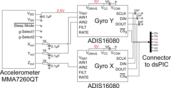
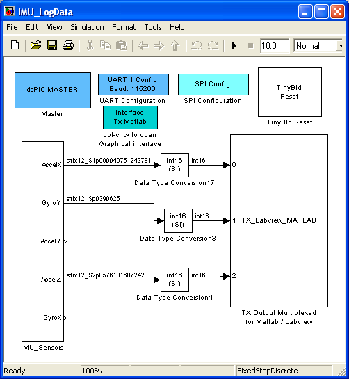
This IMU use three sensor : One Three axial accelerometer and two one axis rate gyro. The accelerometer is powered by the 2.5V analog refference of the 'Y axis' rate gyro. Complementary FilterDownload the three models described abore here with sample of sensor's data. The aim of this complementary filter is to provide a method to implement a model on the dsPIC that has been previously improved thanks to the use of the simulation capabilities of simulink. Simulation uses real data logged by the dsPIC peripheral (same electronic circuit, same noise etc...) Log real dataThe model IMU_LogData is compiled and the resulting .hex file is charged into the dsPIC (using the boot loader tinybld).
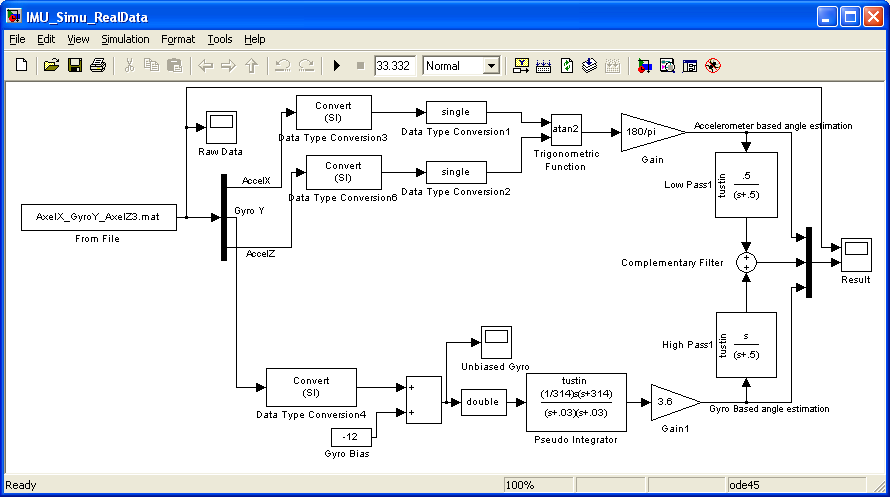
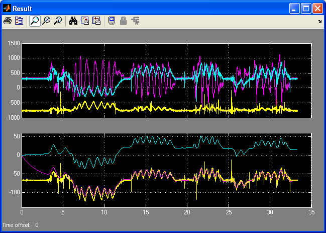
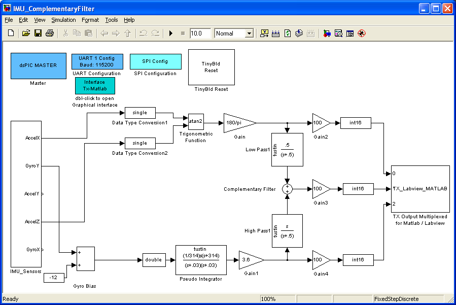
Data are converted again into double or single to simplify the design at this step. The upper part of the model estimates the Y axis angle computing the atan of the X and Z accelerometers values. Because we use the Atan function, the two accelerometer axis do not need to be scaled. The only constraint is that the X and Z acceleration share the same scaling. The lower part of the model estimate the Y axis angle integrating the Y rate gyro. The dynamic of the gyro (low pass filter) is compensated for. The rate gyro is also high pass filtered to remove most of the DC part. The complementary filter, two first order filter (high pass and low pass) with cut off frequency at 0,08Hz. The final estimation of the angle is the addition of the resulting values from theses two filters. The result is presented in pink on the lower part of the following figure.
Complementary Filter running on dsPICTo design the filter for the dsPIC, the two precedent models are mixed up. The filter is inserted by copy-past into the first model used to log data.
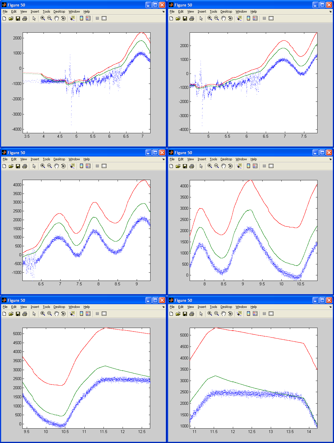
Logging dara resulting from this filter running on the dsPIC, we get the following curves :
The estimated angle using accelerometers (blue curve) is quite noisy. However, it steady value is correct. The estimated angle relying on the integration of the gyro is clean but drift (red curve). Note that the dsPIC has just been switch on and the High pass filter of the pseudo integrator of the gyro has not yet removed the remaining DC bias of the gyro. The DC biais of the Gyro has probably change due to non constant temperature in my house. (I do not have a clim in my tiny room which is in a roof in Marseille ! ). Thus, the gyro integrated angle is slowing drifting away from its real value. The green curve that use both data is clean and driftfree. Its dynamics is as fast as the gyro dynamic. Note that at the beginning, the High pass filter (with a higher bandwidth than the gyro pseudo-integrator high pass filter) has not yet removed the gyro bias. However, at the end of the animation(11 secondes long: from 3,5 to 14,5), both curves (blue and green) are merging as in the simulation. RemarksThe integration of the gyro should be done after the high-pass filter of the complementary filter. This filter placed before the integration would avoid to get high value in the integration internal computation. High value with floating point data mean that the calculation lose its precision. The high-pass filter of the complementary filter has been placed at the end for reason of simplicity and to compare easily the estimation of the angle with the three methods ( integrating gyro, using accelerometer, or by combining both). All calculation are done in double data type or single data type. Theses float data slow down the calculation and use a large amount of memory. It is quite powerfull with the help of simulink to build a fixed point complementary filter. Thus, next step is to go back to the simulation model and to design a fixed point complementary filter ! (using the matlab fixed point toolbox) ConclusionProgramming dsPIC or PIC24 becomes exciting and fun with this toolbox. I do not have to worry with the time consumming configuration of the dsPIC peripheral ! I can focus on simulink simulation, on Real time Workshop capabilities, and on fixed point optimization. Futur work :I am planning to improve this IMU ( fixed point, kalman filtering ? ) and then, to use it in an autopilote for remote controlled glider ( as previous project described on my french website : http://lubink.free.fr) Point to clarify, error, remarks ? Please, leave your comment on the forum !
|