FORUM TOPIC · READ ONLY
Rx Interrupt buffer size
Rx Interrupt buffer size
Forum : Advanced Simulink & RTW Questions
13 message(s) · archive en lecture seule
Hello Lubin,
I understand that the RX circular buffer size can be set from the UART configuration block, but is there a way to configure the UART Rx block to send out more than one byte?
For instance, I don't know if it is possible but I would like to have a buffer of say 256 bytes and have the RX Block send out (every cylce time) 128 new bytes .
Also as a feature request, don't know how hard it could be to have two other outputs from that block, one indicating how full the buffer is (i.e. just a scalar saying how many unread bytes you have) and another saying how many new bytes you sent out the Rx block in this time-step.
Thanks!
I understand that the RX circular buffer size can be set from the UART configuration block, but is there a way to configure the UART Rx block to send out more than one byte?
For instance, I don't know if it is possible but I would like to have a buffer of say 256 bytes and have the RX Block send out (every cylce time) 128 new bytes .
Also as a feature request, don't know how hard it could be to have two other outputs from that block, one indicating how full the buffer is (i.e. just a scalar saying how many unread bytes you have) and another saying how many new bytes you sent out the Rx block in this time-step.
Thanks!
Re: Rx Interrupt buffer size
Hi Mariano,
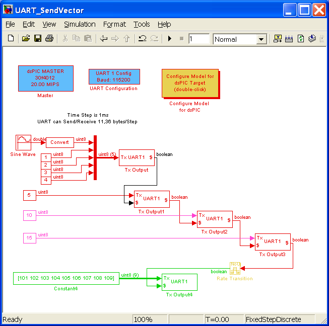
It is possible to send more than one byte within one time step:
See example attached below
I can add the two outputs you request but I could not do it before September. (In vacation)
Using a multirate model, you should be able to do the task without the requested feature.
One short example with the parameters of the model attached:
- time step is 1ms
- UART speed is 115200
==> From the UART Configuration block, you can read that you are able to send and/or receive 11.36 bytes/TimeStep that is 11.36 bytes/ms
When you send 128 data, only 11 bytes will be sent during the first time step. You have to wait 128/11.36 = 12 Time step.
Thus, the part of the model that sends the 128 data should be configured with a time step of 12ms. In this way, you are sure that all data will be sent.
The model attached is an example of mulitrate model: the Green blocks time step is 3ms. The red blocks time step is 1ms.
I hope it helps you.
Let me know if it is Ok. Anyway, I will have a look in September on the requested features
Lubin
It is possible to send more than one byte within one time step:
See example attached below
I can add the two outputs you request but I could not do it before September. (In vacation)
Using a multirate model, you should be able to do the task without the requested feature.
One short example with the parameters of the model attached:
- time step is 1ms
- UART speed is 115200
==> From the UART Configuration block, you can read that you are able to send and/or receive 11.36 bytes/TimeStep that is 11.36 bytes/ms
When you send 128 data, only 11 bytes will be sent during the first time step. You have to wait 128/11.36 = 12 Time step.
Thus, the part of the model that sends the 128 data should be configured with a time step of 12ms. In this way, you are sure that all data will be sent.
The model attached is an example of mulitrate model: the Green blocks time step is 3ms. The red blocks time step is 1ms.
I hope it helps you.
Let me know if it is Ok. Anyway, I will have a look in September on the requested features
Lubin
Re: Rx Interrupt buffer size
Hello Lubin,
I hope you are enjoying your vacation :-). Thanks so much for your quick response. This example will help a lot thanks! And will solve another question I had.
But going back to my original question (and feature request) which is reletad to the RX block and not the TX block as you showed. The idea is that since I have an interrupt driven RX block and between sample times I can receive any amount of bytes between zero and the Max number possible based on the baud rate (MAX_POSSIBLE). I was wondering if I could "empty" the RX buffer on every cycle (without the need of a multirate), let me explain a bit more clear:
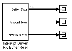
Assume that based on the baud rate and my sampling time I can get any ammount of bytes between 0 and 14 per cycle (i.e. between the last time I checked the buffer and now). For this I foresee 3 possible cases:
1.- I did not receive any byte.
2.- I received any amount of less then 14
3.- I received 14 bytes
It is clear that, since Simulink does not let signal dimensions change at run time, then for cases 1 and 2 the output of the proposed block needs to pad the data with a predefined value (or zeros) and must have a way to tell me how many bytes are actually new. Finally an output telling me how many new UNREAD bytes remain in the buffer might be useful to monitor if I am close to overflowing (or overwriting rather) the circular buffer. This I think would make the interrupt driven really useful since it would let you configure a buffer, have it receive between cycles (via the interrupt) and then poll it every cycle for N new bytes. In that way I can pass on to another function streams of bytes larger than 1 byte (say for instance for GPS decoding which is what I am currently working on).
I have added a "drawing" of how the proposed block would look for the above example. Hope that I have been able to explain myself :-)
Thanks!
I hope you are enjoying your vacation :-). Thanks so much for your quick response. This example will help a lot thanks! And will solve another question I had.
But going back to my original question (and feature request) which is reletad to the RX block and not the TX block as you showed. The idea is that since I have an interrupt driven RX block and between sample times I can receive any amount of bytes between zero and the Max number possible based on the baud rate (MAX_POSSIBLE). I was wondering if I could "empty" the RX buffer on every cycle (without the need of a multirate), let me explain a bit more clear:
Assume that based on the baud rate and my sampling time I can get any ammount of bytes between 0 and 14 per cycle (i.e. between the last time I checked the buffer and now). For this I foresee 3 possible cases:
1.- I did not receive any byte.
2.- I received any amount of less then 14
3.- I received 14 bytes
It is clear that, since Simulink does not let signal dimensions change at run time, then for cases 1 and 2 the output of the proposed block needs to pad the data with a predefined value (or zeros) and must have a way to tell me how many bytes are actually new. Finally an output telling me how many new UNREAD bytes remain in the buffer might be useful to monitor if I am close to overflowing (or overwriting rather) the circular buffer. This I think would make the interrupt driven really useful since it would let you configure a buffer, have it receive between cycles (via the interrupt) and then poll it every cycle for N new bytes. In that way I can pass on to another function streams of bytes larger than 1 byte (say for instance for GPS decoding which is what I am currently working on).
I have added a "drawing" of how the proposed block would look for the above example. Hope that I have been able to explain myself :-)
Thanks!
Re: Rx Interrupt buffer size
Hi Mariano,
Weather is not great for the moment here, but waves are here (Anglet,France)
I didn't read carefully the 1st message. Anyway, I am sure the response may provide useful information.
From the Rx point of view, your suggestion is interesting and very clear. I may also have a look on September on it.
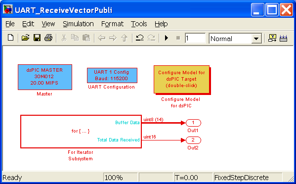
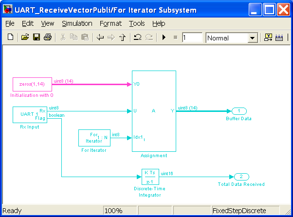
However, I could also propose a "Simulink" Solution. Note that I did not test this solution with a for loop iterate but I think it should work (let us know!).
Note that you could also use a multirate system to execute this "for loop" subsystem every 10ms for example. That would make you able to receive a complete trame at once.
I would be interested to know the solution chosen to parse the GPS input string. Do you plan to use a "Simulink based parser", Stateflow, or are you going to build your own C function? I am also thinking about adding a cheap GPS onboard my reduced model airplane...
Let me know if the solution works and if I should plan to modify the Rx block in September ;-) (With the proposed Simulink solution, you do not have access to the internal Rx buffer state)
Lubin
Weather is not great for the moment here, but waves are here (Anglet,France)
I didn't read carefully the 1st message. Anyway, I am sure the response may provide useful information.
From the Rx point of view, your suggestion is interesting and very clear. I may also have a look on September on it.
However, I could also propose a "Simulink" Solution. Note that I did not test this solution with a for loop iterate but I think it should work (let us know!).
Note that you could also use a multirate system to execute this "for loop" subsystem every 10ms for example. That would make you able to receive a complete trame at once.
I would be interested to know the solution chosen to parse the GPS input string. Do you plan to use a "Simulink based parser", Stateflow, or are you going to build your own C function? I am also thinking about adding a cheap GPS onboard my reduced model airplane...
Let me know if the solution works and if I should plan to modify the Rx block in September ;-) (With the proposed Simulink solution, you do not have access to the internal Rx buffer state)
Lubin
Re: Rx Interrupt buffer size
Thanks Lubin! I will try this and report back. I am planning on writing the GPS reader/decoder in a C function. Once I have it ready I will post it as an example and see if I can get any feedback from you or anybody else in the forum.
Thanks!
Thanks!
Re: Rx Interrupt buffer size
Hi Lubin,
Your example UART_SendVectorPubli here is similar to what I am attempting. Here are my questions:
1.
Regarding UART Tx, do the block ordering inputs ond outputs control the sequence of data sent out the UART port? In your example, first send the Tx Output, followed by Tx Output1, followed by Tx Output2, followed by Tx Output3, etc?
2.
How does the Tx Output handle the 5-wide Muxed data?
Thanks,
John
Your example UART_SendVectorPubli here is similar to what I am attempting. Here are my questions:
1.
Regarding UART Tx, do the block ordering inputs ond outputs control the sequence of data sent out the UART port? In your example, first send the Tx Output, followed by Tx Output1, followed by Tx Output2, followed by Tx Output3, etc?
2.
How does the Tx Output handle the 5-wide Muxed data?
Thanks,
John
Re: Rx Interrupt buffer size
Hi John,
Ordering of blocks whoses input/output are not in relation i.e. when the input of block A do no depends on the output of block B and reciprocal... Ordering is not defined in a way that either block A or B could execute first.
dsPIC blocks Ordering Input/Output option allow to add constraint order. Thus, Tx Output will execute in the order you mentionned.
You can show the code ordering block with : Format ==> Block displays ==> Sorted Order. You will get two number in the upper right corner of each block. The first one is the execution context ("which sampling slot") and he second one is the execution order within a "slot".
Similar to have 5 different Tx blocks with a bigger buffer.
Il all cases, Tx block will block if all data can't be buffered, until first data are sent and buffer is full with last data to send.
Thus, using interrupt may provide a bigger buffer
Lubin
Citation : resodad
Regarding UART Tx, do the block ordering inputs ond outputs control the sequence of data sent out the UART port? In your example, first send the Tx Output, followed by Tx Output1, followed by Tx Output2, followed by Tx Output3, etc?
Ordering of blocks whoses input/output are not in relation i.e. when the input of block A do no depends on the output of block B and reciprocal... Ordering is not defined in a way that either block A or B could execute first.
dsPIC blocks Ordering Input/Output option allow to add constraint order. Thus, Tx Output will execute in the order you mentionned.
You can show the code ordering block with : Format ==> Block displays ==> Sorted Order. You will get two number in the upper right corner of each block. The first one is the execution context ("which sampling slot") and he second one is the execution order within a "slot".
Citation : resodad How does the Tx Output handle the 5-wide Muxed data?
Similar to have 5 different Tx blocks with a bigger buffer.
Il all cases, Tx block will block if all data can't be buffered, until first data are sent and buffer is full with last data to send.
Thus, using interrupt may provide a bigger buffer
Lubin
Re: Rx Interrupt buffer size
Thanks.
Here is what I am trying to do. Sensor data comming in UART1, see attachment 1 for oscilloscope views.
8-bit data ranges 0 to 255 decimal; separeate hundreds, tens, and ones digits and transmit the ASCII equivalent out UART2 followed by comma and space.
I am not sure how to do it. See attachment 2 for my Simulink model.
Eventually, I would like to append data from other sensors to the UART2 output stream.
John
Here is what I am trying to do. Sensor data comming in UART1, see attachment 1 for oscilloscope views.
8-bit data ranges 0 to 255 decimal; separeate hundreds, tens, and ones digits and transmit the ASCII equivalent out UART2 followed by comma and space.
I am not sure how to do it. See attachment 2 for my Simulink model.
Eventually, I would like to append data from other sensors to the UART2 output stream.
John
Re: Rx Interrupt buffer size
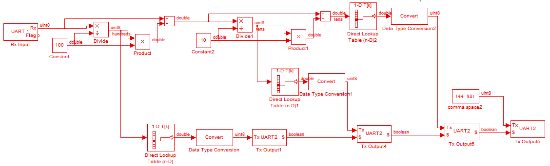
I posted an image of your model that run on Evidence Flex Board (They gracefully provide one for me, so many thanks)
From UART config blocks, you can get how many data can be read at each time step.
Model run here at 2Khz that is a time step of 0.5ms.
@ 115200, you can send or receive 5.68 bytes within one time step.
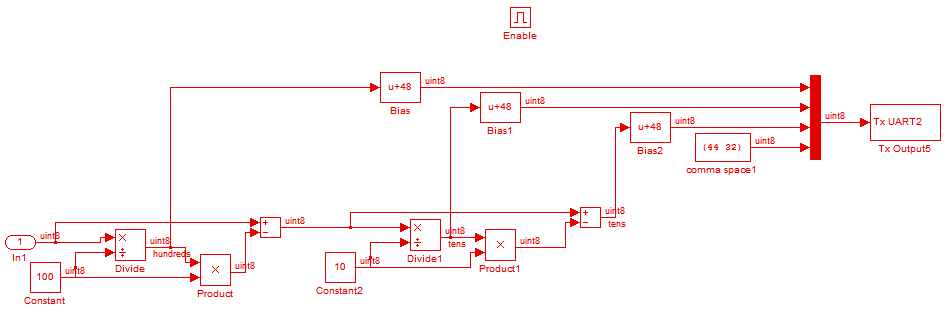
The model is here awaiting for only one data (uint8) that will produce its decimal representation with added a coma and a space: thus, it produce within each time step 5 data
2 potential problems :
1) What if no data are received on the UART1 within one time step?
==> The model will generate the five data that will be 0 as the output Default parameters of the Rx block is set to 0. It may be the last received value if the output default parameter of the Rx block is set to -1.
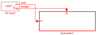
You probably want no output data when there is no input data. Thus, use the flag of the UART block to enable a subsystem where you place this part of the model.
2) What if 5 data [1 2 3 4 5 ] are received on the physical Rx line (UART 1) within one time step?
The Rx block will only output the first data [1]. This is quite good as you could not generate more than 5 data on the output within one time step.
Data [2 3 4 5} are not lost and the second one is on the Rx block output on the next time step. Use interrupt with a large buffer is you are to receive lots of data at once (like 20 data at full 115200 speed).
Anyway, I post a proposition of model. I did not test it, but give it a try.
Other solutions exist, for example just checking the Blocking Function of the Rx block to avoid the enabled subsystem. However, nothing could run in parallel with this last solution!
Lubin
From UART config blocks, you can get how many data can be read at each time step.
Model run here at 2Khz that is a time step of 0.5ms.
@ 115200, you can send or receive 5.68 bytes within one time step.
The model is here awaiting for only one data (uint8) that will produce its decimal representation with added a coma and a space: thus, it produce within each time step 5 data
2 potential problems :
1) What if no data are received on the UART1 within one time step?
==> The model will generate the five data that will be 0 as the output Default parameters of the Rx block is set to 0. It may be the last received value if the output default parameter of the Rx block is set to -1.
You probably want no output data when there is no input data. Thus, use the flag of the UART block to enable a subsystem where you place this part of the model.
2) What if 5 data [1 2 3 4 5 ] are received on the physical Rx line (UART 1) within one time step?
The Rx block will only output the first data [1]. This is quite good as you could not generate more than 5 data on the output within one time step.
Data [2 3 4 5} are not lost and the second one is on the Rx block output on the next time step. Use interrupt with a large buffer is you are to receive lots of data at once (like 20 data at full 115200 speed).
Anyway, I post a proposition of model. I did not test it, but give it a try.
Other solutions exist, for example just checking the Blocking Function of the Rx block to avoid the enabled subsystem. However, nothing could run in parallel with this last solution!
Lubin
Re: Rx Interrupt buffer size
Thanks. The use of enabled subsystems might work, but I think my problem with my own models and with the one you just posted is this:
I can not control the sequence of the data going out UART2. Muxed signals to UART Tx seem to mix up bits producing bad output. Ordered Tx blocks are not working--it appears that the earlier ones are transmitting and the program never gets to the later ones even if I use a large step time. I tried many variations including a series of enabled subsystems controlled by out-of-phase square wave triggers.
I don't see why the ordering ot Tx blocks is not working; maybe I don't understand the intent.
My colleague is suggesting a "For Iterator" to contol processing byte-by-byte. I have not tried it yet. I would like to hear your ideas. His proposal is this:
set a for loop with N=11 for 11-byte Rx messages, and nest another for loop within to separate digits and insert commas and spaces, and Tx.
Regards,
John
I can not control the sequence of the data going out UART2. Muxed signals to UART Tx seem to mix up bits producing bad output. Ordered Tx blocks are not working--it appears that the earlier ones are transmitting and the program never gets to the later ones even if I use a large step time. I tried many variations including a series of enabled subsystems controlled by out-of-phase square wave triggers.
I don't see why the ordering ot Tx blocks is not working; maybe I don't understand the intent.
My colleague is suggesting a "For Iterator" to contol processing byte-by-byte. I have not tried it yet. I would like to hear your ideas. His proposal is this:
set a for loop with N=11 for 11-byte Rx messages, and nest another for loop within to separate digits and insert commas and spaces, and Tx.
Regards,
John
Re: Rx Interrupt buffer size
Citation : resodad set a for loop with N=11 for 11-byte Rx messages, and nest another for loop within to separate digits and insert commas and spaces, and Tx
It may works, however three remarks:
1) Theses nested for-loop are going to take more time than one time step. Thus, you will not respect real-time constraints. Are you planning to run some signal processing at the same time?
2) How do you know that there is a data at the Rx ? you will need an enable subsystem !
3) finally, it's quite complicated and you should avoid that
Citation : resodad Muxed signals to UART Tx seem to mix up bits producing bad output
Weird. When I am looking at the generated code, all seems Ok.
Citation : resodad Ordered Tx blocks are not working
Also weird:
check order in simulink : Format ==> Block displays ==> Sorted Order it is Ok
Check generated code report: it seems also Ok.
Anyway, the problem may come from the UART speed which is not 100% compatible with the quartz used:
The closest UART speed to 115200 achieved by the dsPIC is 113636. That is an error of 1.36% of relative speed error. It is not a lot, but depending on peripheral connected to the dsPIC, it may cause problems.
Or,
There may be a bug in the interrupt of the UART software, but that would be quite a surprise as this part of code has been used for a very long time now and seems to be 100% ok.
Thus, I would suggest making some test by sending constant value through the UART to make sure the problems do not come from the UART error speed.
If you connect constant to an UART Tx block, make sure that you set a sampling rate of the constant block to something like .001. It must be different from -1 or 0 otherwise the model is likely to send only one data at startup! (This is a comon error)
Another simple test is to connect the Rx block to the Tx block and check it’s working (just add 1 to the receive value before to send it to make sure that you are reading the correct value)
Lubin
Re: Rx Interrupt buffer size
Thanks.
I don't know what those "Errors" came from, maybe I was not viewing output data corretly.
Here is a file that appears to be working now. Sorry, but I dont know how to insert images directly in the forum here. See the attached files.
John
I don't know what those "Errors" came from, maybe I was not viewing output data corretly.
Here is a file that appears to be working now. Sorry, but I dont know how to insert images directly in the forum here. See the attached files.
John
Re: Rx Interrupt buffer size
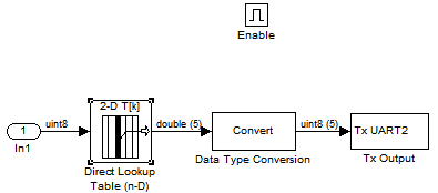
Thanks for your detailed explanation.
This is a quite original solution that will be very fast. As this dsPIC has a lot of memory, it's just fine like this.
You may optimize a bit by storing data of the lookuptable in the uint8 format (enter uint8(T) ).
Lubin
This is a quite original solution that will be very fast. As this dsPIC has a lot of memory, it's just fine like this.
You may optimize a bit by storing data of the lookuptable in the uint8 format (enter uint8(T) ).
Lubin