| |
Change Notification block
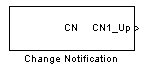
Description
The Change Notification (CN) block allow to detect a change on one or several inputs. This peripheral can also be used to measure the duration of a pulse (like PWM) on all CN ports of dsPIC / PIC24. Note that this block used in PWM input mode is less robust than Input Capture peripheral.
Dialog Box
-
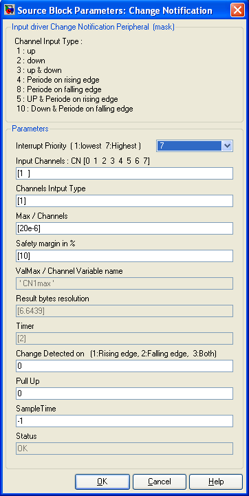
Specify Change Notification channel(s) (CN) starting from 1. Specify multiple channels
as a vector. This will also set the block's number of output.
-
Channel Input Type
-
Select for each channel which measurement you want to extract.
1 : get the High pulse duration
2 : get the Low pulse duration
3 : get both High and low pulse duration
4 : get the periode using rising edge
8 : get the periode using falling edge
5 : get both High pulse duration and periode
using rising edge
10 : get both Down pulse duration and periode using falling edge
The position value in the vector refers to corresponding channel defined in "Input Channels".
-
Max/Channels
-
Define for each channel the max time in secondes of the slowest event to be measured by the corresponding channel.
-
Safety Margin in %
-
Add a margin to the max time defined previously. This margin time allow correct measurement, provided the event is larger than the max attempted value.
-
ValMax / Channel Variable Name
-
This Variable will be evaluated in the workspace and allow you to scale the data.The ValMax is the max value that will be given by an event of the duration defined in Max/Channels. This value does not take into account the Safety margin.
-
Result Byte Resolution
-
This is the log2 of the ValMax Variables for each channels (corresponding to the number of bits coding the information).
-
Timer
-
This is the timer which is used by the corresponding channel. It is set automatically when the diagram is updated or compiled. The timer prescaler are defined in the Master block.
-
Change Detected on
-
Add outputs to the block. For each channel, you can know if a change appears. The output is set to 1 either on rising edge, falling edge or both.
-
Pull up
-
for each channel, 1 mean internal Pul-up resistor connected ; 0 mean Pull up not disconnected.
-
Sample Time
-
-1 mean inherited
-
|
The Microchip name PIC, dsPIC, and MPLAB are
registered trademarks of Microchip Technology Inc.
MATLAB, Simulink, and Real-Time Workshop are
registered trademarks of The MathWorks, Inc.
| Lubin Kerhuel 's Website |
Contact : [adresse e-mail retirée] |
|
|


